High-Fidelity Electromagnetic Simulation of Indirect Lightning Effects on Military Aircraft Wiring Systems

lightning effects on aircraft

Military aircrafts are struck by lightning on average 10.5 strikes with an estimated occurrence every 10,000 flying hours in Europe. While lightning strikes are common, aircraft are designed with extensive lightning strike protection to safely conduct the high currents and electromagnetic fields and protect critical systems and pilot. Full-scale physical lightning testing is costly and can delay design corrections, while scaled models often fail to replicate full-size responses accurately. Virtual testing through advanced electromagnetic and multiphysics simulation enables engineers to study lightning effects on aircraft structure and cables efficiently, optimizing protection strategies without extensive physical prototypes.

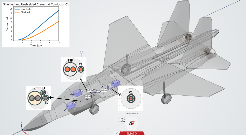
Ansys EMC Plus can comprehensively evaluate electromagnetic behaviour on complex platforms when analyzing lightning effects on aircraft, including radiated coupling to cables, radiated emissions from cables, and coupling through shields, as well as EMI crosstalk between adjacent harnesses. The tool also supports studies of coupling from static discharges and high-intensity radiated fields (HIRF) into cables and equipment interfaces, enabling engineers to assess both cable signal integrity and lightning-induced transients at critical system ports in a single, integrated workflow [1].

Lightning and its effects on Aircrafts

Lightning is a natural atmospheric discharge phenomenon characterized by large transient currents produced at the interface between regions of intense positive and negative charge accumulation within cloud (Intra Cloud Lightning) or between clouds (Inter Cloud Lightning) and between the cloud and the ground (CG Lightning). During a lightning strike, the current can rise extremely rapidly—on the order of 10–20 kA/µs. Lightning activity is especially frequent within the troposphere (0–12 km altitude) and the lower stratosphere, which coincide with the primary flight altitudes of commercial and military aircraft. This high occurrence rate means that aircraft are regularly exposed to lightning environments.
Approximately 90% of CG lightning strikes are downward negative lightning, meaning they transfer negative charge from the cloud to the ground. In this type of lightning, the negative charge accumulates at the base of the cloud, and when the electric field strength exceeds the dielectric breakdown of air, a stepped leader propagates toward the ground. Once a conductive path is established, a high-current return stroke flows upward from the ground, neutralizing part of the cloud’s negative charge. Downward negative lightning is the most common type observed worldwide and is of particular concern for aviation because it is the form most likely to interact with aircraft flying at altitudes within the troposphere, where these discharges occur. The conductive skin of an aircraft acts as a Faraday cage, shielding its occupants from stray electrical charges by offering a low-resistance path for electrons to flow into and out of the structure.

Lightning effects on aircraft are generally divided into two primary categories. Direct effects refer to the physical damage caused at the lightning attachment point. In contrast, indirect effects arise from the electromagnetic coupling of the lightning current with onboard systems and wiring, producing transient disturbances that can interfere with or degrade the performance of electronic and electrical components. Lightning can also cause several critical hazards that affect various aspects of an aircraft’s operation and safety. It can lead to structural damage by creating punctures or burns in the airframe, compromising its physical integrity. Fuel system hazards arise if lightning ignites fuel tanks, increasing the risk of fire or explosion. Crew incapacitation is also a concern if lightning interferes with cockpit instruments or causes electrical shocks. Engine failure can result from lightning strikes damaging engine components or causing control system malfunctions. Additionally, thermal damage from the intense heat generated by lightning can weaken materials and critical systems, further endangering the aircraft. Aircraft manufacturers conduct extensive lightning strike simulations using tools like Ansys EMC Plus prior to production to mitigate risks from downward negative lightning.

Stages in Aircraft Lightning Attachment Simulation

The three stages of aircraft lightning simulation—pre-processing, EM simulation, and post-processing can all be completed within a single interface in Ansys EMC Plus. Pre-processing involves preparing the model for simulation by assigning material properties and cable harness location to create the computational model. It also includes defining other simulation parameters such as current source, mesh settings, and probes. In the simulation step, FDTD solver is used to calculate the fields around the aircraft [2]. It allows user to model complex geometries in very less time. It uses voxel mesh terminology. Multi Conductor Transmission Line Solvers is used to solve very complex cables. In the final stage, post-processing, the simulation’s results are transformed into a format suitable for direct comparison with measured data or for conducting additional analysis.
lightning effects on aircraft
Figure 1: Lightning Attachment Simulation Stages on a Military Aircraft

Current Waveshape and Lightning Attachment

Lightning waveforms used in aircraft simulations typically follow a double-exponential shape, and Ansys EMC Plus supports several standard versions of these waveforms to model the indirect effects of lightning on aircraft systems. In this study, the simulation employs a double-exponential waveform with a 218 kA peak current and an approximate rise time of 6.4 µs, as this combination represents one of the most severe and therefore worst-case scenarios for assessing lightning-induced transients in aircraft wiring. Aircraft certification under SAE ARP5412 uses these Waveform for Zone 1 and 2A areas, where attachment points experience full current intensity.

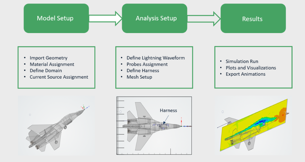
In accordance with SAE ARP5414, the aircraft structure is divided into lightning strike zones that classify the severity and type of lightning attachment expected at various locations. The aircraft nose is designated as Zone 1, which represents a primary attachment zone where lightning is most likely to strike and where the initial high-amplitude current waveform is expected to enter the aircraft. A lightning flash enters an aircraft at one point and exits at another. For simulation in this article the standardized current waveform is injected at the aircraft nose. This approach enables a realistic evaluation of indirect lightning effects on aircraft wiring, supporting compliance with industry standards and ensuring the robustness of system designs against lightning-induced disturbances.

lightning effects on aircraft
Figure 2: Aircraft Wiring Harness Configuration and Resulting Conductor C1 Current for Shielded and Unshielded Cases

Cable Layout & Shielding Terminations

Ansys EMC Plus provides advanced capabilities for cable and end terminations in electromagnetic compatibility analyses, making it particularly effective for simulating lightning-induced transients in aircraft wirings. Cables are simulated using a hybrid FDTD-MTL approach. Although Ansys EMC Plus supports importing harness data from KBL files for automated cable definition, this analysis employs manual routing for simplicity. Ansys EMC Plus provides an extensive cable library to streamline modeling of common harness configurations. A 16 AWG twisted shielded pair (TSP) cable, along with two 24 AWG bare conductors (C1 and C2), is defined and assigned within the harness according to the corresponding cable geometry. Initially, C2 is provided with a shield, while C1 remains unshielded. The Cable Inspect Cross Section feature in Ansys EMC Plus enables to visualize and verify multi-layer cable bundle geometries along their routed paths.
The Tool allows users to specify resistive, inductive, or complex impedance terminations, ensuring that simulations closely reflect real-world conditions at cable interfaces. Proper definition of end terminations is essential for evaluating current transients on cables. MHARNESS can automatically produce 2D plots of the current measured by probes during simulations, facilitating rapid visualization and analysis of the results. A current probe is placed on conductor C1 to measure the current induced by indirect lightning effects. Initially, the current is measured with C1 unshielded. Subsequently, a shield is applied to C1, and the induced current is measured again. The results indicate that the induced current on the unshielded conductor is higher, highlighting the effectiveness of shielding in reducing lightning-induced transients. Animation probes in Ansys EMC Plus play a crucial role in visualizing the time domain evolution of electric field and electric current across aircraft surfaces during lightning simulations.
For reducing computational effort, certain simplifying assumptions were adopted in the aircraft model used for the simulations. A reduced-scale CAD representation of the aircraft was employed in place of the full-scale geometry, which significantly lowers mesh density and reduces the overall computational domain, thereby decreasing simulation time and memory requirements. In addition, the cabling system was modeled using a simplified harness representation and the cable current responses are presented over the first 10 µs to emphasize the fast-front coupling effects.
Figure 3: Visualization of Lightning-Induced Aircraft Body Currents

Lightning Probability Simulation Capability

EMC Plus delivers advanced lightning probability simulation capabilities for mission-critical applications through seamless integration with Ansys STK. This approach goes beyond traditional Lightning Attachment Simulation and Aircraft Lightning Zoning Analysis by evaluating lightning strike probability along the complete aircraft mission profile. The automated Lightning Probability workflow enables users to run a full simulation with a single click, significantly streamlining the analysis process. By computing lightning strike probability along an aircraft’s trajectory for specific missions, the solution provides actionable insights to support effective risk mitigation and mission planning.

Conclusion

Ansys EMC Plus offers a robust solution for evaluating lightning-induced indirect effects on aircraft cables. By simulating Zone 1 strikes with cable routing and shielding tests, it enables accurate assessment and mitigation of induced currents. The Tool allows visualization of electromagnetic field and electric current propagation, validation of harness designs, reducing reliance on costly full-scale tests. Compliant with standards, EMC Plus supports the development of safer, lightning-resilient aircraft while saving time and cost in the design process.

Reference Links