
Uncover the physics of air breakdown using Ansys Charge Plus. This blog explains how to model discharge, charge transport, and breakdown events for high-voltage system design. Air breakdown occurs when the electric field between two electrodes exceeds the dielectric strength of air, causing ionization and rapid current flow—commonly observed as arcing or sparking. Predicting this effect is crucial for designing reliable high-voltage systems, preventing insulation failure, and mitigating ESD risks. One way to quantify the breakdown voltage is Paschen’s Law. Paschen’s Law describes how the breakdown voltage of a gas depends on the product of pressure and gap distance between two electrodes. It states that for a given gas and electrode material, the voltage required to initiate a discharge is not constant but varies with the pressure–distance (pd) factor. Paschen’s Law is crucial in high-voltage engineering, vacuum systems, and aerospace applications, as it helps predict insulation behaviour under varying environmental conditions. By leveraging Ansys arc simulation capabilities, engineers can visualize discharge behavior, predict breakdown conditions, and design safer, more reliable high-voltage systems with confidence.
Ansys Charge Plus provides a physics-based environment for simulating charge accumulation, discharges, and breakdown events within air and other dielectrics. The Ansys Charge Plus is a Tool with multiple solvers.
Utilizes Time-Domain Solver for extracting dynamic electric fields and simulating arcing phenomena. The algorithms in a FDTD solver are tied directly to the lattice. The lattice is made up of intersecting lines that are parallel to the coordinate axes.
Features a Non-Linear Air Chemistry Module that represents the ionization and recombination reactions responsible for air breakdown at various air densities, temperature and humidities. Non-linear Air Chemistry Module looks at the dielectric’s breakdown during arcing.
Employs Coupling of 3D Particle Transport and Finite Element Methods (FEM) to simulate Internal Charging Processes. 3D Particle Transport is used to look at molecular level things flowing into and out of specific regions in the model. Dielectric breakdown simulation employs using the coupling of the FEM with the 3D Particle Transport and a Stochastic Tree Model.
Implements Radiation Hardening (Rad-Hard) Simulations and evaluate changes in material properties to meet the required radiation tolerance. Uses Particle Tracking feature to Track different particles like electron, Proton or Photon. Charge Plus includes an automatic workflow for Radiation Hardening.
Supports streamlined workflows, from CAD import and material assignment to meshing and sophisticated result analysis—all embedded within the Ansys Discovery interface.
Geometry Creation: Ansys Charge Plus is embedded within the Discovery environment, making it easy to import CAD models in .STEP or other formats. After import, the model should be examined for accuracy, though it is also possible to create a model from scratch using the Edit and Sketch tools in Discovery. Geometry can be modified using tools such as Pull, Move, Combine, and others, providing flexibility for quick design adjustments.
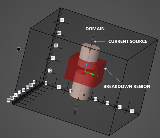
Initialization of Domain: The simulation domain should fully encapsulate the model. When the domain is first defined, it automatically surrounds the geometry, though its size can be adjusted as needed. The mesh size is determined by the domain’s step size, which defines the mesh cell dimensions along the three Cartesian axes. The Mur 1 H-Field boundary condition is applied when the current source is placed perpendicular to the boundary. This boundary condition absorbs any radiated fields from the current source, preventing reflections and ensuring accurate simulation results.
Material Assignment: An Isotropic material (Copper), which is linear and frequency-independent, is applied to the top and bottom electrodes. EMA3D Tab contains a built-in library of materials that enables users to assign accurate physical properties for simulation. Users can alter material properties or add their own, making the library flexible for research and industry-specific analysis. Materials can be easily selected or modified from the simulation tree within the Discovery interface.
Setting up of Current Source: First, a wire geometry is created from the center of one electrode to the top surface of the lattice, followed by another wire geometry from the center of the second electrode to the bottom surface of the lattice. Current sources are then assigned to these wire geometries, after which the desired waveforms are specified. The directions of both current sources must be aligned; if they are found to be opposite, the direction of either source should be reversed.
Defining Breakdown Region: Within the simulation domain, the Breakdown Region is a localized area where the non-linear air environment is specified using non-linear air chemistry module. Identify region in the model where breakdown is expected and configure the non-linear air chemistry module at that place. This breakdown region models the physical conditions under which air becomes conductive due to strong electric fields.
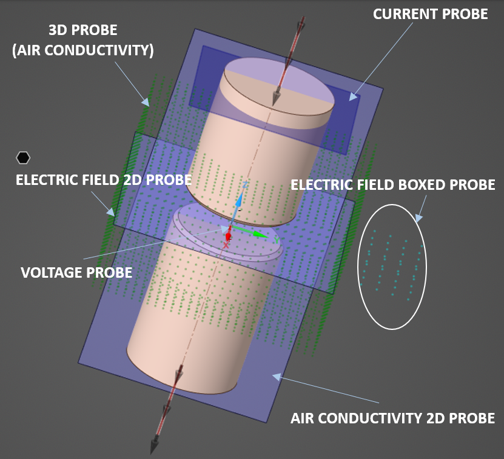
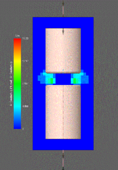
Probes Setup: Six probes are defined to gather data during the simulation. First, a voltage probe is created, followed by the definition of Animation Probe (Electric Field), Boxed Probe (Electric Field), Bulk Current Probe, Animation Probe (Air Conductivity), 3D Probe (Air Conductivity). 3D Probe superimposes the results on the geometry after running the simulation. Clipping planes slice through the results to find the region for users to inspect.
Meshing and Running Simulation: The air breakdown simulations employ the FDTD mesh, which consists of a structured grid of hexahedral elements. Once the simulation is started, EMA3D performs pre-processing and generates the files required to run the simulation. The preprocessing status, along with any errors or warnings, is displayed in a pop-up window. If an error occurs, close the window, resolve the issue, and then restart the simulation. After pre-processing is complete run the simulation.
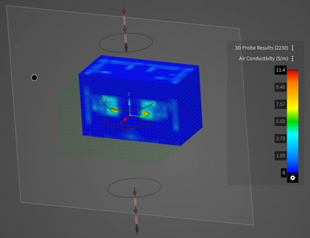
Results and Visualizations: After meshing the model and running the simulation, the next step is to display the results. Boxed probe will generate 2D plot for electric field during or after simulation. The plot displays the mean, maximum, and minimum electric field values computed from the data within the boxed region. Animation probes enhance post-processing by enabling 2D display of Air Conductivity and Electric Field. Voltage Probe data can be plotted using EMA3D Connect, and 3D probe data is visualized in ParaView, an open-source platform for data analysis and advanced visualization.
Ansys Charge Plus offers an advanced and efficient solution for modeling air breakdown phenomena, empowering engineers to design safer, more robust electronic and high-voltage systems by simulating critical charge, discharge, and breakdown events with high accuracy. Ansys Charge Plus supports accelerated GPU computing for faster breakdown and conductivity simulations. Charge Plus is designed to handle the electromagnetics and the densities of electrons and ions within the arc itself. To accurately model the propagation of plasma species, neutrals, and the hot air surrounding the arc, it is necessary to integrate Ansys Charge Plus with Ansys Fluent.
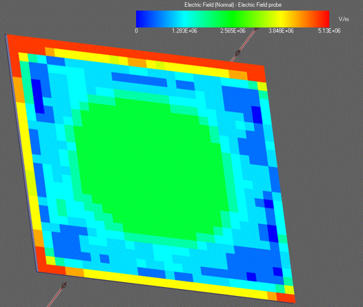
Figure 6 : Visualization of Air Conductivity in ParaView